


VIPA MICRO
The compact, fast small control system
CPU FACTS
• PROFINET IO-Controller and I-Device
• Integrated web server for device diagnosis and web visualisation
• Ethernet PG/OP channel for active and passive communication
• 16 digital inputs, DC 24V with integrated status display
• 12 digital outputs, DC 24V 0.5A with integrated status display
• 2 analogue inputs 0V … +10V, 12Bit
• 4 channels for counters, frequency measurement and 2 channels for pulse width modulation
• 64 Kbytes integrated working memory, extended up to 128 Kbytes
• I/O address range, digital/analogue 2048 bytes
• 512 timer/meter, 8192 bit memory bytes
• Low dissipation power, max. 7W
• External memory ability with SD card (up to 2GB)
• Programmable via VIPA SPEED7 Studio, Siemens SIMATIC Manager or Siemens TIA Portal
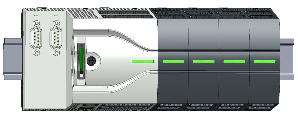
System Overview
The System MICRO is a modular automation system for assembly on a 35mm mounting rail. By means of periphery modules this system may be adapted matching to your auto- mation tasks. In addition, it is possible to expand your CPU by appropriate interfaces. The wiring complexity is low, because the DC 24V electronic section supply is integrated to the backplane bus and this allows replacement with standing wire.this text to edit it.
Components
DON'T KEEP ON GOING ROUND AND ROUND contact us for more information about the products and services that we can supply Tel 02476 980833
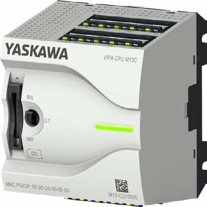
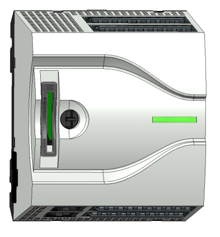
CPU
With the CPU electronic, input/output components and power supply are integrated to one casing. In addition, up to 8 periphery modules of the System MICRO can be con- nected to the backplane bus. As head module via the integrated power module for power supply CPU electronic and the I/O components are supplied as well as the electronic of the periphery modules, which are connected via backplane bus. To connect the power supply of the I/O components and for DC 24V electronic power supply of the periphery modules, which are connected via backplane bus, the CPU has removable connectors. By installing of up to 8 periphery modules at the backplane bus of the CPU, these are electrically connected, this means these are assigned to the backplane bus and con- nected to the DC 24V electronic power supply.
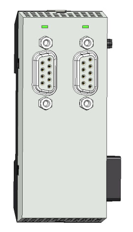
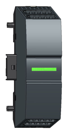
Extension Module
By using extension modules you can extend the interfaces of the CPU. The attachment to the CPU is made by plugging on the left side of the CPU. You can only connect one extension module to the CPU at a time.
DON'T KEEP ON GOING ROUND AND ROUND contact us for more information about the products and services that we can supply Tel 02476 980833
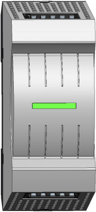
Power Supply
The power supply can be mounted together with System MICRO components at the mounting rail. It serves for electronics and power supply.
Periphery Module
By means of up to 8 periphery modules, you can extend the internal I/O areas. The attachment to the CPU is made by plugging them on the right side of the CPU.
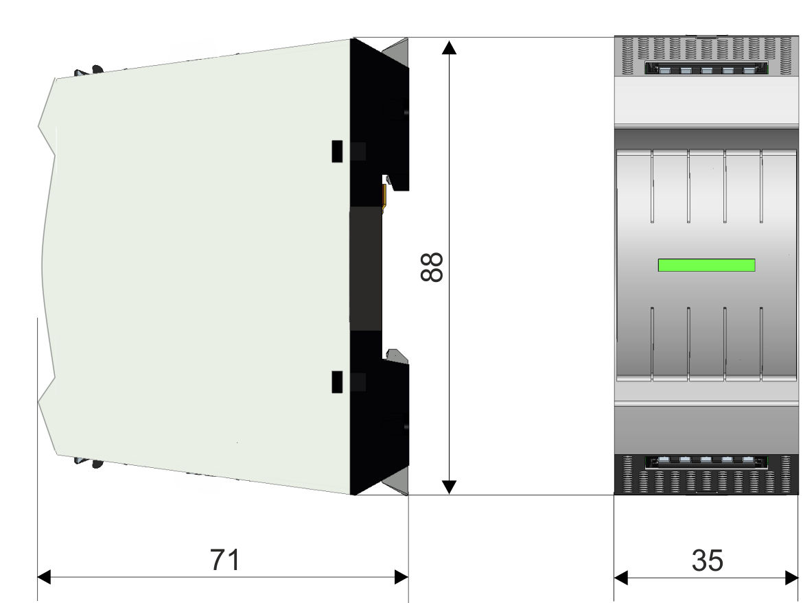
Dimensions CPU M13C
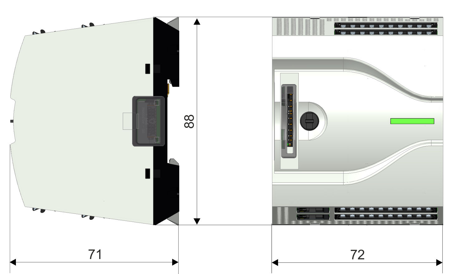
Dimensions in mm
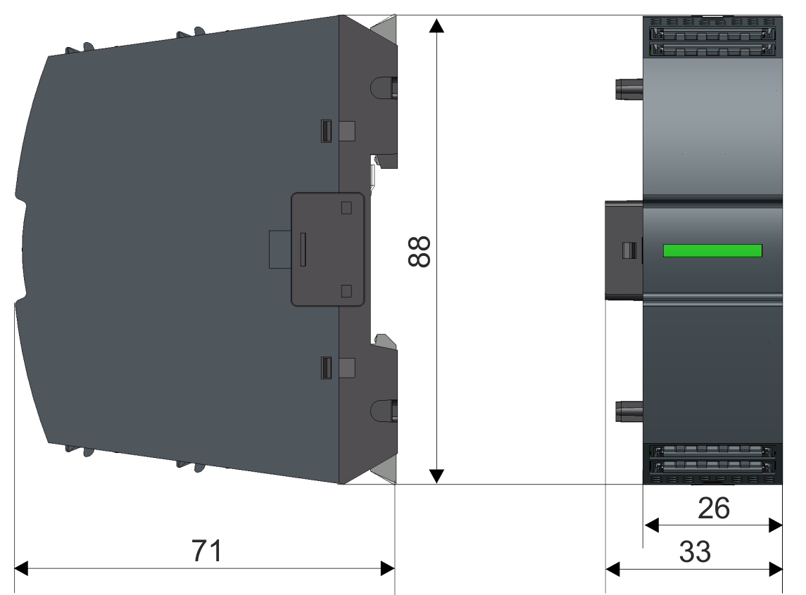
Dimensions extension module EM M09
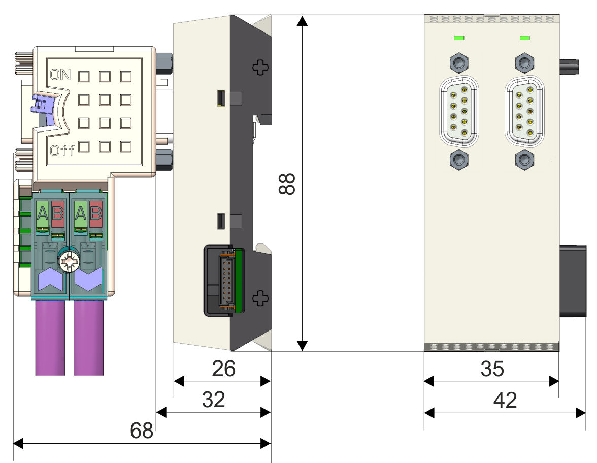
Dimensions in mm
DON'T KEEP ON GOING ROUND AND ROUND contact us for more information about the products and services that we can supply Tel 02476 980833
Dimensions Power Supply
Dimensions in mm
Dimensions Periphery Module
Dimensions in mm